9 Sliced Image
A few years ago I made a helper utility for myself to automatically detect Scale 9 borders for sprites. It unexpectedly turned out to be in demand among my colleagues, and I kept meaning to find time for a few tweaks and improvements. Unfortunately, free time showed up only when I was in the painful process of looking for a new job. As it usually happens, a small 15‑minute “adventure” that was supposed to end quickly somewhere between interviews and doing test tasks turned into a full-blown investigation - and eventually into this article.
Why do we need this?
First, let’s figure out what it is and why it really matters for your UI (and why I ask artists every time: “Do we really need a gradient on this button?”).
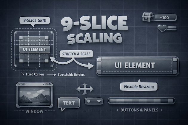
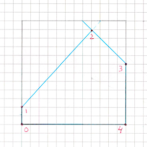
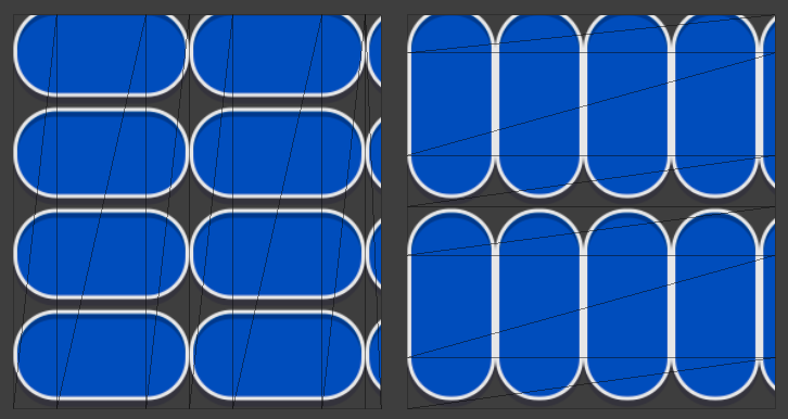
Scale 9 (9-slice scaling, scale9grid, etc.) is an image rendering technique that, according to Wikipedia, was first introduced in Macromedia Flash 8. That’s where I first encountered it. The idea is that the image is split into 9 independent regions, which are rendered with different scaling. This lets you change the image size without losing visual quality - in particular, we preserve rounded corners and border thickness.
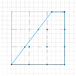
More visually:
It’s a perfect fit for many UI elements: buttons, window backgrounds, sliders, bars, popups, etc.
Scale 9 itself is just a concept that can be implemented in different ways. In most rendering engines (including Unity) this is done via the standard UV mapping mechanism and additional geometry: extra vertices are added to the original image quad so that the mesh is split into 9 regions with their own UVs. After that, all the “dirty” scaling work is handled by the GPU.
I’ll also note that there are even fairly exotic solutions like 25-slice.
Why is it important?
- First and foremost, it lets you build a good responsive UI. We no longer need to guess text sizes for container sizes and wait for artists to prepare separate variants for every locale. UI layouts are often drawn for English, and then suddenly, at the very end of development, German or some other “long” locale appears - and the whole team makes interesting discoveries. With Scale 9 we get a choice: shrink the font size (artists usually resist), increase the container size, or try to find a reasonable visual compromise.
- We can reduce the physical texture size to the minimum by trimming the central areas down to a single pixel in width/height. For scalable regions that’s enough: they’ll be stretched or tiled anyway. This positively affects GPU memory usage and CPU → GPU bandwidth - you need to transfer and store substantially fewer pixels.
- Smaller textures take less space in the build. If you have lots of UI sprites, the build size savings can be noticeable.
- It’s easier to fit smaller textures into one atlas. This:
- reduces the number of atlases and potentially loading time,
- increases the chance that the UI batcher can combine more elements into a single batch (fewer material and texture switches).
Here I’ll make a small digression. My utility is exactly about automatic detection of Scale 9 borders and trimming the texture down to the necessary minimum.
It’s important to note that it also can automatically trim extra transparent areas around the edges of the image. When exporting to PNG, artists often forget to do this and deliver sprites in the dimensions of the original PSD, with large transparent margins on the sides. For UI, this is a common cause of performance issues:
- such sprites take more space in texture memory and in atlases,
- because of large transparent rectangles it’s very easy to get lots of overdraw, which hurts fillrate and loads the GPU more than needed.
As a result, we spend resources drawing “nothing” - empty transparent pixels that simply could have been absent. Automatically trimming such areas is a simple but very effective optimization step.
Off-the-shelf solutions
UI.Image
As a direction for further improvements to my utility, I chose automatic migration of UI.Image in prefabs and scenes. The point is that when you trim a sprite down to minimal dimensions, the UI breaks everywhere that an Image did not have Image.type = Sliced. This makes the utility rather problematic to use on large, already-laid-out interfaces.
And here I ran into the first compatibility problem with my idea around UI.Image:
we can’t use Fill and Sliced at the same time on the same component. The image type is a single enum, and you have to pick one: Simple, Sliced, Tiled, or Filled.
If the same sprite is used both where we need Sliced (for example, a button background) and where we need Filled (some progress bar), then we can no longer aggressively reduce the physical texture size without breaking one of the cases.

SlicedFilledImage
Reasonably deciding that I wasn’t the first to run into this problem, I went to Google and quickly found a gist by the author of many useful Unity utilities. It’s a SlicedFilledImage component that tries to combine sliced and fill.
But a quick look at the code showed that it wouldn’t be that easy. Essentially it supports only linear filling scenarios:
- direction is set by an enum
FillDirection { Right, Left, Up, Down }, - there are no equivalents of
Image.FillMethod.Radial90/180/360that the standardUI.Imagehas.
In real life, radial fills for 9-slice sprites aren’t needed every day, but formally this breaks full compatibility of such a component with the original UI.Image.
Inheriting from UI.Image
So I decided to come at it from another angle: just inherit from the original UI.Image and override a few of its methods. And here I again ran into the traditional pain of extending anything in Unity: heavy use of internal and private where protected methods and a slightly more open architecture would help a lot.
On one hand, hiding implementation details from the external user is absolutely logical and healthy. On the other - when you want to neatly override a small piece of Image behavior, you suddenly find out that:
- most of the interesting logic is hidden in private methods and internal utilities,
- important fields and helpers are inaccessible to subclasses,
- and to slightly change behavior you end up copying hundreds of lines of code and several helper structs into your class, instead of one neat override.
This is not only unpleasant from a maintenance perspective, it also slightly impacts build size: every such “fork” of a standard component adds yet another chunk of almost identical code (especially noticeable in WebGL, where every extra kilobyte counts).
At some point it becomes clear that there aren’t many options left: you have to open the UI.Image sources and make your own improved version.
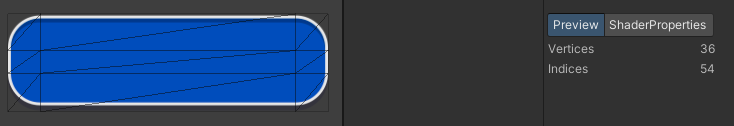
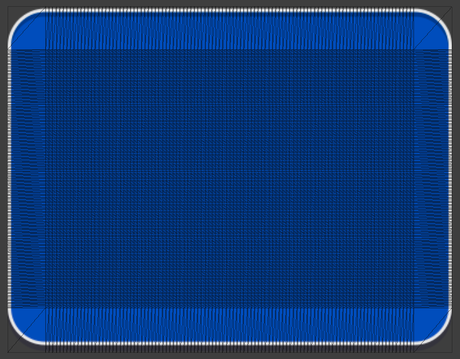
And while reading the sources I made my first small discovery about UI.Image being suboptimal: a sliced image is assembled from 9 separate quads without vertex sharing. That is:
- logically, 9-slice is a 3×3 grid that can be represented by 4×4 vertices (16 vertices total, with border vertices shared),
- but the current
GenerateSlicedSpriteimplementation runs a double loop over 3×3 and callsAddQuadfor each quad, which adds 4 new vertices and 2 triangles.
As a result, instead of the theoretically sufficient 16 vertices per mesh we get 36. This is, of course, a micro-optimization and in most projects it won’t be the bottleneck. But:
- it costs us almost nothing to make an implementation that reuses vertices (especially if we’re already writing our own
Image); - and sometimes vertex budgets are so tight that even every extra hundred in the UI is already an argument.
Writing our own component
Basic rendering
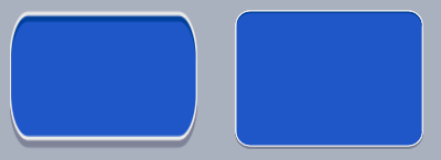
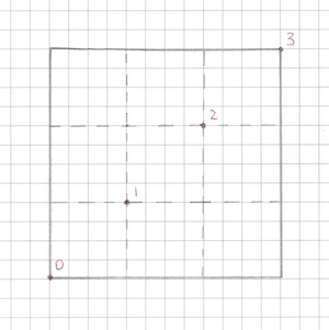
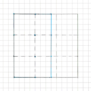
As we figured out earlier, in terms of the mesh, the Simple and Sliced variants of the same image differ only by the presence of intermediate vertices:
Simplecan be represented as one quad (4 vertices),Slicedis the same rectangular area, but split by a 3×3 grid, i.e. with extra “inner” edges.
Therefore we don’t need a separate complex code path for each mode: one mesh generator is enough, which, depending on the type, simply includes or skips intermediate vertices. You can roughly see how UI.Image computes the parameters for all vertices here. Essentially it takes only 4 significant diagonal vertices and builds the whole grid from them.
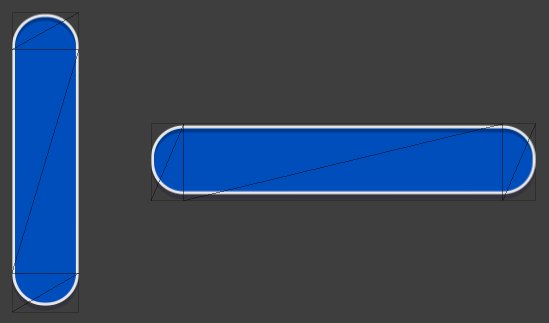
Here comes the first micro-optimization. In the standard implementation, Sliced mode always draws 9 quads (a double loop for (x=0..2) for (y=0..2)), even when it’s redundant.
However:
- if the
Imagesize exactly matches the sprite size (on both axes), - and we aren’t stretching it wider or taller than the original bounds,
then we don’t need any “rubber” areas - the image can be drawn with a single quad, even if the sprite has 9-slice borders set.
If we generalize the idea a bit, then:
- the need to add intermediate vertices along a particular axis arises only when the RectTransform size along that axis differs from the sprite size;
- if along some axis the scale is 1:1 (for example, the
Imageheight equals the sprite height), we don’t need a grid along that axis - two “outer” coordinates are enough.
This, by the way, is a very common real-world scenario: the same horizontal progress bar, where the height is almost always fixed to the sprite’s art size, and only the width changes. With this scheme, our custom component can:
- add intermediate vertices along X (we need to stretch the center),
- and along Y use only top/bottom, like
Simple.
So we save a bit in cases where the standard UI.Image still generates an “honest” 3×3 grid.
Filling
Alright, we can now draw a Sliced image - and we even do it slightly more efficiently than the native component. Now we need to handle filling.
The standard UI.Image has different code paths for each fill mode. And I’ll be honest: I got very lazy to dive into every branch separately (though in the end I still had to follow the overall line of thought and partially repeat it). So I rather quickly came to the idea of inventing a generalized mechanism that would power all fill modes.
Let’s look at two of them:

And here’s what that looks like on our vertex “grid”:
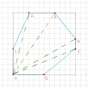
If we abstract it, we get the following picture:
- our image is a vertex grid of arbitrary size (at this stage it’s either 2 vertices along an axis or 4, but we don’t want to hard-branch the code for each configuration and immediately write everything for an arbitrary grid size - this will be very useful later);
- the fill mode is one or several half-planes, inside which vertices are considered “visible”;
- in addition to existing vertices, new vertices appear at the intersection points of these half-plane boundaries with the edges of our grid.
Moreover, there can be (and in some cases must be) multiple such half-planes: for example, in radial modes it’s convenient to describe a sector as the intersection of several bounding half-planes.
After some thinking and experimentation I arrived at the following algorithm:
Let the grid have
nvertices horizontally andmvertically. Create a buffer of sizen * mand fill it with grid vertices in a strictly defined (fixed) order.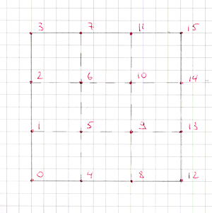
This grid contains
(n - 1) * m + n * (m - 1)edges. We also fix the order of these edges and assign each one an index.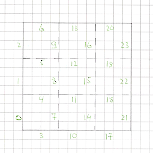
We’ll process each grid quad separately, so we create one more buffer of size
edgesCount * cutsCount. We’ll cache found intersection points of the “cut” lines with edges there.. This is needed so that adjacent quads during triangulation use a shared point on a shared edge, rather than creating duplicates.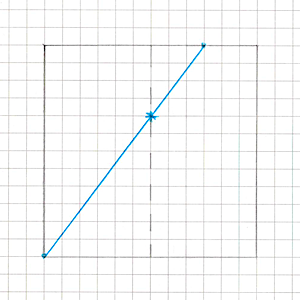
- Next, for each quad:
- Create two vertex buffers -
vertexBuffer1andvertexBuffer2- of size4 + cutsCount. This is the maximum number of vertices if all half-planes intersect the quad (each time we “clip off” a corner of a convex polygon, it gains one more vertex).
- Fill
vertexBuffer1with the quad’s original four vertices. In each vertex we additionally store information about the edges adjacent to it within this quad (their index(es) in the global edge list) so we later know which cache cell to write the intersection into. - For each half-plane:
- Walk the vertices of the current polygon clockwise and compute the sign of the
dotproduct for each vertex. This tells us whether the current and previous vertices lie inside the half-plane.- If both vertices are inside the half-plane - just add the current vertex to
vertexBuffer2. - If only the previous vertex is inside - that means the edge crosses the half-plane boundary, and we need to add an intersection point. We:
- compute the intersection parameter from the two
dotproducts (interpolate the segment parametertfrom them), - interpolate position and UV by
t, - before writing, look into the intersection cache by edge index: if the point already exists - reuse it, otherwise store and cache it,
- add this point to
vertexBuffer2.
- compute the intersection parameter from the two
- If only the current vertex is inside:
- first compute and add the intersection point (the same way as above),
- then add the current vertex.
- If both vertices are inside the half-plane - just add the current vertex to
- After walking all vertices and processing one half-plane,
vertexBuffer2contains the updated polygon, already “clipped” by this half-plane.
- Walk the vertices of the current polygon clockwise and compute the sign of the
- Swap
vertexBuffer1andvertexBuffer2so thatvertexBuffer1again holds the current vertices. - Repeat clipping steps until we process all half-planes.
- Create two vertex buffers -
- When all half-planes for the quad are processed,
vertexBuffer1contains the final convex polygon. Walk its vertices and for each determine whether it has already been written into the final mesh. Vertices that haven’t yet been written are added toVertexHelper(the helper object uGUI uses to build UI meshes) and we remember their index for subsequent triangulation. - Important point: our quads are, by definition, convex quadrilaterals. The intersection of a convex polygon with half-planes also always yields a convex polygon. This property is critical because then we don’t need complex triangulation algorithms - we can safely use fan triangulation:
- take the first vertex of the polygon as the “central” one,
- and sequentially build triangles of the form
(v0, v(i), v(i+1))forifrom 1 tocount - 2.
- After all quads are processed we get the final “clipped” mesh - a grid with all outside areas cut away that don’t fall into the specified half-planes.
Grid cutting
Temporary buffers and stackalloc
Here I want to make an important note. The standard UI.Image uses fixed-size static arrays for temporary buffers - that’s great for its own rigidly limited scenarios, but in our case it’s not very convenient: we’re aiming for arbitrary grid sizes and any number of cutting half-planes.
At the same time, in basic scenarios that replicate UI.Image behavior, these buffer sizes remain fairly small. To avoid poking the GC and creating short-lived heap allocations, I decided to use stack allocation.
This is very convenient for performance, but also quite dangerous: with an unlucky configuration (too large a grid, too many half-planes) you can get a stack overflow (StackOverflowException) and effectively crash the Unity process.
So I added extra safety:
- if the temporary buffer size does not exceed ~4 KB (which looks like a reasonably safe threshold), I use
stackallocand work with a stack array; - if more is required - instead of the stack I take a buffer from a pool on the heap, so as not to risk overflow.
This approach lets typical cases stay allocation-free and fast, while not turning “exotic” cases into a time bomb for the whole application.
However, you shouldn’t forget that buffers taken from a pool need to be cleared beforehand in cases where you don’t expect them to be completely filled. I spent several hours debugging a very strange bug in caching shared intersection points before I realized that it would be a good idea to clear this buffer before using it.
Fill mode variations
Now we have everything we need to implement absolutely any filling types on top of our grid.
Vertical and Horizontal are implemented very simply: it’s just one line along one axis, whose normal is directed according to fillOrigin. We move this line within the image rectangle proportionally to fillAmount, and our half-plane “cuts off” the excess part of the mesh.
Radial90
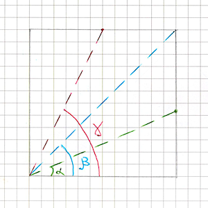
Now let’s look at Radial90. The name itself suggests that in this mode fillAmount is the fraction of an angle from 0 to 90 degrees (more precisely, from 0 to π/2). At first I confused myself: I tried to compute a point on a circle from this angle, tried different radii, but no matter what circle I used, the result still didn’t match what UI.Image draws.
It turned out to be much simpler: fillAmount defines an angle inside the image rectangle, not on some abstract circle. We just need to compute its sin and cos - and then pure trigonometry:
- if
cos > sin, the boundary of the filled area “slides” along the opposite vertical edge; - if
cos < sin, along the opposite horizontal edge; - if
cos == sin, the line hits exactly the corner.
Here the UI.Image sources helped me a lot: this exact logic is implemented there for Radial90. The only funny detail is that fillAmount is first multiplied by 90° (in degrees) and only then converted to radians. Mathematically we don’t care about degrees at all: you can multiply by π/2 right away and work in radians. But in the end it’s just another constant in the transformation chain - it doesn’t change the algorithm, it just makes the code slightly harder to read.
Tests
During the unsuccessful experiments with a circle, I realized this was the perfect moment to write tests. The more new functionality I added, the harder it became to visually verify that my component behaved exactly like UI.Image (and for us full compatibility matters!). In an ideal world you start with tests, but we don’t live in an ideal one - which, however, doesn’t diminish their importance :)
For each Image.type I made several parameterized Editor tests. From these parameters we create a sprite, a UI.Image, and my component. Then we:
- for each component separately, take a camera snapshot into a texture,
- compare the resulting textures pixel-by-pixel.
To simplify debugging, failing tests save both textures to disk as PNG so I can later open them calmly and see what exactly went wrong.
Also, for some modes I cared about, I added Asserts on vertex count to be sure my implementation in the worst case creates no more vertices than UI.Image.
Such checks protect well against accidental regressions: if somewhere in the code I suddenly stop sharing vertices or start generating extra polygons, the test will report it immediately, even if visually the image still looks “fine”.
Later this helped more than once to quickly find bugs both in my implementation and cases of strange behavior in UI.Image itself (we’ll get back to that).
Radial180
Now we can calmly return to fills and watch the number of passing tests grow.
Radial180 is actually quite easy to implement on top of Radial90.
Intuitively it’s just two 90° quarters glued together.
If we mentally split the rectangle into two halves (depending on fillOrigin this is either the top/bottom or left/right segment), then:
- for
fillAmount <= 0.5we fill the first half like a normalRadial90; - for
fillAmount > 0.5:- the first half is already fully filled,
- in the second half we draw another
Radial90, but withfillAmountremapped to[0, 1]for the remaining 50%.
In the end, Radial180 boils down to two Radial90 calls with different rectangles and sector orientations.
The main care point here is choosing which half to process first and how to account for fillOrigin and direction (fillClockwise) so that the result matches the standard UI.Image behavior exactly.
Radial360
At first Radial360 seemed only slightly more complex than Radial180.
The idea suggests itself: just like in the previous case, split the rectangle into two halves and apply Radial180 to each.
But there’s a nuance: now we need to additionally separate these halves from each other with one more cut. And everything works great until we set fillAmount > 0.5.
At that moment the resulting shape stops being a convex polygon, and our half-planes start to conflict with each other: intersections and clipping order become ambiguous, and the previous logic that relied on convexity stops being reliable. Problem.
But solvable.
To avoid breaking the general approach and avoid complex triangulation for non-convex shapes, I took a more direct route: I started treating each half as a fully independent set of vertices.
- each half of the rectangle gets its own vertex set;
- for each half, we run the half-plane clipping logic separately;
- in the end, we render two independent convex polygons that together form the required 360° sector.
Formally, we lose a bit of optimality here:
- we get extra non-shared vertices along the central axis (between halves),
- i.e. we can no longer fully share geometry between them.
But in practice tests show the resulting geometry is no more complex than UI.Image:
in the worst case the number of vertices and triangles remains comparable or even cheaper. And if we fit into the same budgets as the standard component, performance is fine.
Tiling
In general, Tiled mode doesn’t bring any special difficulties and fits well into our overall pipeline.
The idea is:
- fill the base mesh vertices as if the image size were equal to one tile size, applying 9-slice immediately if needed;
- then “lay out” the remaining tiles by simply shifting them by an integer number of tiles along the axes (position offset always equals tile size);
- and for each of these tiles, apply our cutting half-planes separately.
Sharing vertices between tiles won’t work here:
vertices that occupy the same XY position will have different UVs, because each tile uses its own local region of the texture.
If the tile size is not a divisor of the RectTransform size along one axis, we need to add one extra cut for each such axis to “trim” the excess so tiles don’t extend beyond the target rectangle.
The standard UI.Image implementation in Tiled mode allows setting tile size only as the original sprite size. For us, there are no fundamental limitations:
- we can make tile size arbitrary,
- and also add
spacing- gaps between tiles.
Here another optimization is relevant, which UI.Image already does.
If the source sprite texture has TextureWrapMode.Repeat (and in our custom variant also zero spacing and tile size equal to sprite size), then there’s no need to draw tiles as separate meshes - we can use one quad with UVs that go beyond [0, 1] (for example, (0, 0)–(N, M)).
But it’s important to remember a nuance:
TextureWrapMode.Repeatworks only for a sprite that is not in an atlas.- In the editor you may see your
Tiled Imagedrawn as one quad with repeating UV. - But in a build the sprite will most likely be packed into a Sprite Atlas, and the real texture becomes
Clamp- then the engine is forced to render tiles as a bunch of separate quads.
As with Sliced mode, I used a small micro-optimization and check whether UV repeat is possible per axis separately:
- if along X the conditions allow it (wrap=Repeat, spacing=0, tile size matches the sprite), we can tile along X via UV>1 without creating extra vertices;
- and along Y we can still use explicit tiles, or vice versa.
This lets us slightly reduce geometry in cases where the standard UI.Image always picks one option globally.
The True Purpose of Tiled
By this point I had already run into strange and at first inexplicable UI.Image behavior in Tiled mode when the sprite has borders. Basically, the image looked not like “classic” tiled, but like Sliced, and with insanely complex geometry. Initially I decided it was some weird UI.Image bug, temporarily muted tests for this case, and was already preparing the package update.
But in the end curiosity won. Especially since this code path is explicitly written in the UI.Image sources - so it’s not a bug, but deliberate behavior.
I started reading the documentation more carefully and realized that all these years I had been understanding Tiled mode wrong. Its behavior was originally intended to be similar to Sliced, with the inner areas being tiled instead of scaled. It’s just that when a sprite doesn’t have 9-slice borders, it gets tiled as a whole. At the same time, the documentation recommends using a sprite without borders so you don’t run into geometry issues. Overall, it’s pretty confusing and not very obvious. Essentially:
- corners behave like
Sliced; - edges and center are not stretched, but repeated;
In practice I’ve never once had a real need for this mode, but since it exists and is clearly intended, there’s nothing left to do but rework my pipeline to correctly support this scenario. It’s quite possible someone somewhere actually uses it.
Essentially, only the function that fills the base image changes, before we apply tiling and cut with lines:
- before, we had an almost fixed grid size (2 to 4 vertices per axis),
- now it becomes truly arbitrary - the grid can expand however it needs to fit all repeated segments.
It gets especially “fun” if the inner 9-slice area is trimmed down to 1 pixel: in that case, as the RectTransform grows, the number of tiles and thus vertices grows monstrously. Unity honestly hints at this in the old docs: at large sizes in Tiled mode it generates a mesh limited to about 16,250 quads - beyond that tiles start getting larger so it doesn’t exceed the geometry limit.
And this is where our ArrayBuffer came in handy: in such scenarios (complex Tiled + borders, huge grid, tons of tiles) we can easily exceed the safe limit and trigger a stack overflow and crash.
Thanks to the wrapper that can choose between stackalloc and a pooled heap buffer depending on the situation, the heaviest cases automatically move to the heap, and instead of crashing the editor or build we just get slightly more expensive but safe allocations.
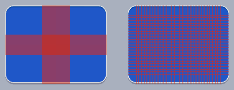
To make the difference between Sliced and Tiled + borders easier to see, I had to tint the sprite’s center area - otherwise they’re visually easy to mix up, especially on simple textures.
And here I want to make a small remark about what I consider a terrible design decision in UI.Image. Essentially, we have a complete change of component behavior in the scene when an asset parameter changes.
I can immediately give two miserable scenarios:
- A project has a sprite the team uses in two places:
- as a normal
Simpleimage, - and as
Tiled.
Then someone decides to optimize the sprite a bit, sets up 9-slice for it, setsborders- and that’s it. Where it wasTiled, it suddenly starts rendering via a completely different scheme: it looks more likeSliced, and with extremely complex geometry made of a huge number of tiles.
The scenario is rather exotic and will most likely be noticed visually.
- as a normal
- A more dangerous scenario, which I’m almost sure exists in real projects.
The sprite initially hasbordersand is intended forSliced. In the scene it’s meant to be used asSliced, but in the inspector someone misclicks and sets it toTiled. Visually - no difference at all: for a sprite prepared forSliced, it will look the same. And you’ll find out only:- either when the final mesh exceeds the ~65k vertex limit (and
UI.Imagestarts complaining), - or if you look at the scene in
Wireframemode and notice the completely insane geometry.
- either when the final mesh exceeds the ~65k vertex limit (and
In my strong opinion, UI.Image should have branched this logic not by whether the sprite has borders, but by its own additional flag, to avoid such non-obvious side effects when working with assets. That’s exactly what I did in my component: an explicit mode switch - an explicit behavior change.
And UI.Image has a bug related to all this, at least in Unity 2021.3.45. If you set a sprite with borders, then in Tiled or Sliced mode you get access to the fillCenter flag and can turn it off. If you then completely remove borders from the sprite, then in Tiled mode nothing renders at all:
- the center isn’t drawn because
fillCenterremained turned off in the component’s internal data, - and the inspector no longer shows this flag (for a sprite without
bordersit simply isn’t displayed), - you can’t turn it back on - there’s no UI option for it at all.
To the user this looks like a “broken image for no visible reason”, while the root cause is somewhere deep inside the borders + fillCenter + selected Image.type combination. In my component I tried to avoid such traps and make behavior more predictable.
Custom filling
As a bonus, I made a small Scriptable abstraction for custom fill modes:
1
2
3
public abstract int GetPolygonsCount(float fillAmount);
public abstract int GetPolygonCutLinesCount(int polygonIndex, float fillAmount);
public abstract void FillPolygonCutLines(Span<CutLine> cutLines, float fillAmount, Rect rect, int polygonIndex);
GetPolygonsCount- reports how many separate polygons we’ll need for the currentfillAmount
(for example, as in the case of the non-convex shape inRadial360, where we split it into several convex parts).GetPolygonCutLinesCount- returns how many cut lines the current polygon will have
for the givenfillAmount(bypolygonIndex).FillPolygonCutLines- fills the providedcutLinesbuffer with parameters of cuts for
the specified polygon at the currentfillAmount. Here we have everything we need:rect- the source image rectangle,polygonIndex- the polygon index,fillAmount- the current fill value.
I recommend in such implementations to carefully watch fillAmount everywhere and not create extra
cuts when they aren’t needed:
- at
fillAmount = 0you can avoid defining cuts entirely and/or return 0 polygons; - at
fillAmount = 1you can often get by with one polygon without additional lines; - in intermediate states - add only the cuts that actually affect the shape.
This not only simplifies computations, but also gives the engine fewer reasons to generate extra vertices and triangles where a simpler case is possible.
Custom Filling
Performance
All that’s left is to run a few performance tests to compare the performance of the new component with UI.Image. The basis for all tests will be an empty scene with a camera and a single Canvas with a child GridLayoutGroup, where we’ll add a specified number of elements. The tests can be split into two categories: static ones, where the components are added at startup and nothing else happens, and dynamic ones, where every frame we change cellSize, thus forcing a mesh rebuild for all components.
I’ll be running the measurements on a MacBook M4 Pro and on a Xiaomi Redmi 8A.
To start, let’s take a very extreme case: 10k objects in Sliced mode, laid out in a full-screen grid, with a recalculation (by changing the cell size) every frame:
| PlayerLoop | Memory | Render batches | |
|---|---|---|---|
| UI.Image | 3140 ms | 154 mb | 7 |
| SlicedImage | 3914 ms | 134 mb | 4 |
Overall, there’s nothing unexpected here: our generalized approach is not free, and rebuilding meshes takes more time. But thanks to the fact that we try to share vertices as much as possible and avoid generating unnecessary geometry, we get:
- lower memory usage;
- fewer render batches (because a single batch can fit more elements with lighter meshes).
The scenario is indeed pretty extreme, but 25% still felt like too much to me. So after spending some time with the profiler, I tried to optimize the computations within reason. Of course, it didn’t come without some code duplication. DRY isn’t always appropriate, especially when we’re talking about performance.
Let’s look at the updated results:
Sliced mode with recalculation every frame:
macOS
| PlayerLoop | Memory | Render batches | |
|---|---|---|---|
| UI.Image (100) | 259 ms | 60 mb | 2 |
| SlicedImage (100) | 259 ms | 60 mb | 2 |
| UI.Image (1000) | 520 ms | 69 mb | 2 |
| SlicedImage (1000) | 520 ms | 65 mb | 2 |
| UI.Image (10000) | 3137 ms | 154 mb | 7 |
| SlicedImage (10000) | 3136 ms | 134 mb | 4 |
Android
| PlayerLoop | Memory | Render batches | |
|---|---|---|---|
| UI.Image (100) | 1051 ms | 26 mb | 2 |
| SlicedImage (100) | 1046 ms | 26 mb | 2 |
| UI.Image (1000) | 6636 ms | 35 mb | 2 |
| SlicedImage (1000) | 7021 ms | 32 mb | 2 |
| UI.Image (10000) | 66571 ms | 125 mb | 7 |
| SlicedImage (10000) | 70978 ms | 92 mb | 4 |
Sliced mode without recalculation every frame:
macOS
| PlayerLoop | Memory | Render batches | |
|---|---|---|---|
| UI.Image (100) | 261 ms | 60 mb | 2 |
| SlicedImage (100) | 259 ms | 60 mb | 2 |
| UI.Image (1000) | 269 ms | 66 mb | 2 |
| SlicedImage (1000) | 268 ms | 65 mb | 2 |
| UI.Image (10000) | 321 ms | 143 mb | 7 |
| SlicedImage (10000) | 322 ms | 123 mb | 4 |
Android
| PlayerLoop | Memory | Render batches | |
|---|---|---|---|
| UI.Image (100) | 1047 ms | 27 mb | 2 |
| SlicedImage (100) | 1049 ms | 26 mb | 2 |
| UI.Image (1000) | 1128 ms | 33 mb | 2 |
| SlicedImage (1000) | 1134 ms | 31 mb | 2 |
| UI.Image (10000) | 1857 ms | 109 mb | 7 |
| SlicedImage (10000) | 1857 ms | 83 mb | 4 |
In static cases, our component behaves exactly like UI.Image, and thanks to vertex reuse it gives a small win in memory and batches. The cost of the computations only really starts to show up when we do them every frame on an Android device with relatively large numbers of components. So I just want to remind you that canvas rebuilds are always an expensive operation, so you should always pay attention to how your UI is split across canvases and try to avoid recalculating things that shouldn’t be recalculated.
Now let’s look at a slightly heavier code path where we need to compute intersections with cutting half-planes.
Radial 360 Filled mode without grid recalculation, but with fillAmount changing every frame:
macOS
| PlayerLoop | Memory | Render batches | |
|---|---|---|---|
| UI.Image (100) | 267 ms | 60 mb | 2 |
| SlicedImage (100) | 259 ms | 60 mb | 2 |
| UI.Image (1000) | 265 ms | 65 mb | 2 |
| SlicedImage (1000) | 268 ms | 67 mb | 2 |
| UI.Image (10000) | 949 ms | 133 mb | 2 |
| SlicedImage (10000) | 1127 ms | 129 mb | 2 |
Android
| PlayerLoop | Memory | Render batches | |
|---|---|---|---|
| UI.Image (100) | 1109 ms | 24 mb | 2 |
| SlicedImage (100) | 1041 ms | 27 mb | 2 |
| UI.Image (1000) | 2262 ms | 28 mb | 2 |
| SlicedImage (1000) | 2499 ms | 30 mb | 2 |
| UI.Image (10000) | 17320 ms | 86 mb | 2 |
| SlicedImage (10000) | 19859 ms | 79 mb | 2 |
Radial 360 Filled mode with grid recalculation and fillAmount changing every frame:
macOS
| PlayerLoop | Memory | Render batches | |
|---|---|---|---|
| UI.Image (100) | 259 ms | 68 mb | 2 |
| SlicedImage (100) | 260 ms | 59 mb | 2 |
| UI.Image (1000) | 468 ms | 64 mb | 2 |
| SlicedImage (1000) | 509 ms | 67 mb | 2 |
| UI.Image (10000) | 2568 ms | 133 mb | 2 |
| SlicedImage (10000) | 2811 ms | 129 mb | 2 |
Android
| PlayerLoop | Memory | Render batches | |
|---|---|---|---|
| UI.Image (100) | 1049 ms | 22 mb | 2 |
| SlicedImage (100) | 1049 ms | 26 mb | 2 |
| UI.Image (1000) | 5846 ms | 28 mb | 2 |
| SlicedImage (1000) | 6329 ms | 30 mb | 2 |
| UI.Image (10000) | 54177 ms | 86 mb | 2 |
| SlicedImage (10000) | 51886 ms | 79 mb | 2 |
In this mode there’s more computation, so the performance difference is noticeable even on a Mac. It’s the inevitable price of universality, which, however, on real UIs with proper splitting across canvases you’ll almost never have to pay. But the choice is yours.
You can run the tests yourself and inspect the results if you plug the package into your project and add it to Packages/manifest.json:
1
"testables": ["com.utkaka.scale-nine-slicer"]
Nuances
There were a couple of small nuances in my implementation.
Vertex count limit
In Tiled + Borders mode, if the final geometry contains more than ~65k vertices, UI.Image automatically makes tiles larger to fit this index buffer limitation (the ushort index limit for mesh indices).
Since my pipeline already differs noticeably from UI.Image’s pipeline, directly copying their behavior turned out to be not so easy. And in most cases, if your UI mesh suddenly starts requiring tens of thousands of vertices, that itself is a good signal that something went very wrong with sprite design or the chosen rendering mode.
So in my component I do it simpler:
- right after filling the base vertices (before tiling and before cutting by half-planes) I check their count;
- if it’s over 65k - I just log an error and render nothing.
Not the most elegant solution, but:
- the case is extremely rare,
- behavior is predictable,
- and I wanted to finally ship the package update instead of losing a few more days supporting very exotic scenarios.
Raycast
The original UI.Image can do raycast against opaque pixels of the image. For this, several conditions must be met:
- the sprite texture must have Read/Write enabled (so it can be read from code),
- the component must have
alphaHitTestMinimumThresholdset to a value between 0 and 1
(at 0 and 1 alpha hit testing doesn’t work), - and you can change
alphaHitTestMinimumThresholdonly from code (the inspector doesn’t show this parameter by default).
In our case, a correct implementation of such a raycast would require:
- either storing all triangles and vertices of the resulting mesh and being able to quickly find ray intersections with them,
- or computing the same geometry “on the fly”, so that when you hit a triangle you can determine the corresponding UV and then the needed pixel in the texture.
I considered this case relatively exotic, and the implementation quite non-trivial in scope, so for now I consciously didn’t implement it. Visually the component is fully compatible with UI.Image, and alpha hit testing is needed much less often.
If any of these limitations is truly critical for you - write in the article comments or create an issue in the package GitHub project. This will help understand which usage scenarios are worth supporting in future versions.
Jittering on tiles
Tests in Tiled modes showed that my tiles have a small, barely noticeable offset. For now I considered it a non-critical flaw and simply muted tests for this case.
Summary
Finally, a small demo of how it all works together:
Full demo
I want to emphasize that my solution does not pretend to be a UI.Image killer. It has nuances mentioned above. And it’s a bit more compute-heavy, but at the same time it can produce slightly more optimal geometry. But it definitely opens up more possibilities when working with 9-sliced sprites.
At the moment I’ve only made an analog for uGUI, but lately UI Toolkit has been gaining popularity, especially in the context of MVVM architectures, of which I’m a fan. So I’ll try to come back to this topic again in the foreseeable future.
But star the GitHub repo and create issues - it really helps keep motivation to work on open source and keep evolving the project.